
Reposted from Viega. Click here for original article.
There are three common types of PEX: PEX-A, PEX-B and PEX-C. There is a widespread misperception that the letters refer to grades of quality and that PEX-A is better than PEX-B which is superior to PEX-C.
Not true. The letters are used to identify different manufacturing processes and have nothing to do with quality or performance. All types of PEX must meet the same minimum standards for pressure and temperature ratings, minimum bending radius and pipe wall thickness and ID/OD dimensions. And all types have to comply with the same ASTM F876 and ASTM F877 standards and SDR9 dimensional standards.
Of course, that doesn’t mean all types of PEX are identical. Each has its own characteristics. All PEX is a polyethylene material which has undergone a change in molecular structure using a chemical or physical process to chemically link the polymer chains. Crosslinking of polyethylene improves PEX properties such as temperature, strength, flexibility etc.
PEX-A is created by introducing peroxide into the HDPE before it’s extruded. Per the ASTM Standard F876, PEX-A must be crosslinked to 70% in order to meet the standard for burst pressure.
PEX-B, like Viega PureFlow, is created through the silane process, which is done after the HDPE is extruded into pipe. Per the ASTM standard F876, PEX-B must be crosslinked to at least 65% to meet the standard for burst pressure.
PEX-C achieves cross-linking through electron beam irradiation. Per the ASTM standard F876, PEX-C must be crosslinked to at least 65% to meet the standard for burst pressure. PEX-C is also prone to cracks and kinking.
Viega PureFlow PEX-B tubing has the flexibility characteristics of PEX-A. PureFlow and other PEX-B tubing has a higher bursting pressure than PEX-A. In addition, PureFlow has the highest chlorine and oxidative resistance of the PEX types, making it the more reliable choice for potable water, radiant heating and other applications, especially when recirculation of domestic hot water is required. Viega PureFlow PEX is also extremely durable, making it an ideal choice for high-traffic construction areas.
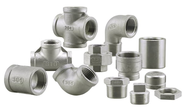
There also are differences in the fittings for PEX types, but we’ll cover that in another post.
When choosing PEX types, pay attention to the benefits.
Reposted from Viega. Click here for original article.
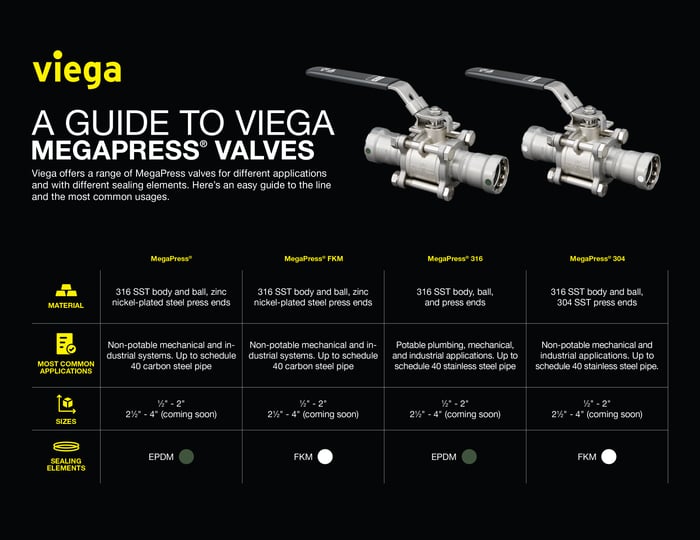
.jpg?width=1200&name=BenifitsSSF(FI).jpg)
 All Pressure switches have two operating points known as the cut-in (Reset Point) and cut-out (Trip Point) settings. The cut-in point is for the falling pressure and the cut-out point is for the rising pressure. Every switch also includes a differential or a range based on the cut-in and cut-out points. Both the cut-in and cut-out on most switches can be adjusted if certain applications require that. For example: if the cut-in is 40 PSI and the cut-out is 60 PSI the differential is 20 PSI.
.png?width=425&name=My%20Post(23).png) exposed thread from the top of the nut to the top of the stud that you are adjusting. Write it in fractions of an inch or mm, this is in case you need to start over so then you know where you started.
exposed thread from the top of the nut to the top of the stud that you are adjusting. Write it in fractions of an inch or mm, this is in case you need to start over so then you know where you started.
