Reposted from BoshartU. Click here for original article.
Ever wondered what the main responsibility of a Well Point is? Since they belong deep down in the ground, you don’t come across them that often once they have been installed. You may not be able to see them work but you have probably run into the water they help produce.
In this blog, we will look closely at the function of a well point and help you verify what size well point is most preferred for your specific application. Well points have a couple different names including Sand Points, Drive Points or Drive Well Points. To not make it too complicated, we will be referring to them as well points throughout the blog.

What are Well Points?
A Well Point is a piece of pipe that has openings large enough to allow water to enter but also small enough to keep the water-bearing formation in place. There are a variety of well point designs but we are going to look at PVC well points and PVC well Screens.
PVC Well Points are commonly found in Residential, Irrigation or Water System applications as they are best used with sand or light gravel. Well points are frequently used by people who own rural or country homes and require their own primary or secondary water supply system.
Depending on the depth and the soil the well points need to travel through, they are paired with either a jet pump or hand pump and drive couplings. The well point is then drove into the ground, passing the soil and clay until it has reached water bearing gravel and sand.
When selecting which well point size opening to go with you will need to determine the granular size of the sand in which it will work with. Typically a screen type well point uses a 60 gauge for coarse sand, 80 gauge for medium sand and 100 gauge for fine sand. Something to keep in mind!
Well Points VS Jet Points
Jet points are extremely similar to well points but the main difference is jet points offer simplicity as they are directly attached to a well screen. This eliminates the added expense of a wash down valve and any other additional materials and labour.
Jet points are uniquely designed to allow for maximum fluid circulation and powerful jetting action. They are most popularly used for quick installation and development of single or multi well monitoring and residential applications.
PVC Well Screens
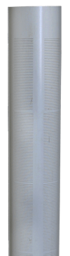
As you can see in the picture on the left, all screens are slotted horizontally in order to provide extreme strength against collapsing due to sand pressure. The horizontal slots also allow more open area per foot compared to vertical slotting. If a screen becomes plugged by aggressive water, they can be cleaned out with ease and without damaging the actual screen. The horizontal screens are most ideal for use in natural or artificial gravel packed wells like irrigation wells, canals and ponds.
Wash Down Valves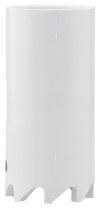
A wash down valve efficiently allows the washing down of well screens for shallow irrigation wells. They can attach to any 1-1/4″ or 2″ well screen or casing. When attached to any source of water pressure, like a garden hose, the female thread allows for an easy one step wash down. Once the water pressure is removed, the internal valve seals off the bottom to prevent any sand from entering.
Being aware of the main function of a well point is a good start to using them to their full potential. Doing research of what exactly a product is before you install it is the key to a successful and smooth installation. Well, any stress free process is the point, right?
Reposted from BoshartU. Click here for original article.
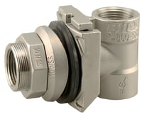
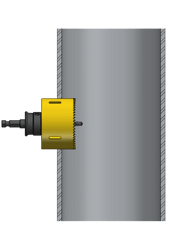
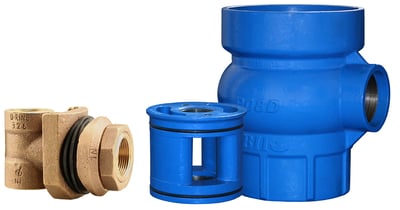
.png?width=250&name=Pitless%20Adapter(1).png) Slide type pitless adapters are very popular and are mainly used in residential and commercial applications up to 2″ drop pipe sizes. The slide pitless is installed through a hole drilled in the well casing. A water tight sanitary seal is made using compression gaskets on both the inside and the outside of the well casing.
Slide type pitless adapters are very popular and are mainly used in residential and commercial applications up to 2″ drop pipe sizes. The slide pitless is installed through a hole drilled in the well casing. A water tight sanitary seal is made using compression gaskets on both the inside and the outside of the well casing..png?width=250&name=My%20Post(172).png) The picture on the right shows an example of a spool pitless adapter
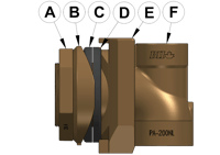
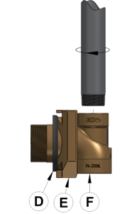
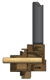
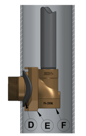
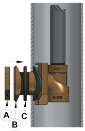
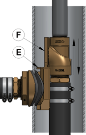
The picture on the right shows an example of a spool pitless adapter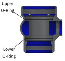 consisting of two components, the spool and the discharge housing. On the left is an example of a complete pitless unit. As you can see in the picture, the spool pitless adapter is installed between the well casing and the upper barrel. The upper barrel is typically 2″ larger than the well casing. A well cap provides a sanitary seal for the well. When all the components are assembled together, it becomes a pitless unit.
.png?width=150&name=WS40%20(top).png)
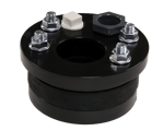 Single Hole: A single hole well seal means there is only one pipe needing to go down the well. This well seal is generally used for installing either a shallow well jet pump or a submersible pump. There are two tappings included on this style of well seal, one is a vent tapping and one is a cable hole tapping for submersible pump installations.
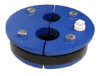 double hole and single hole is the double hole is equipped with one vent tapping only. There is no cable tapping as no wires go down the well on a jet pump installation.
.png?width=250&name=WS62%20(top).png) Initially, all well seals were made from Cast Iron. They were relatively inexpensive and they could be made in different shapes and sizes. Cast Iron well seals are suitable for a majority of installations with pump sets up to 300′ and they are available in split plate design. The downfall is they are susceptible to rust and cracking during installation. They also have a limited strength, they are not best suited for deep pipe sets greater than 300′.
Initially, all well seals were made from Cast Iron. They were relatively inexpensive and they could be made in different shapes and sizes. Cast Iron well seals are suitable for a majority of installations with pump sets up to 300′ and they are available in split plate design. The downfall is they are susceptible to rust and cracking during installation. They also have a limited strength, they are not best suited for deep pipe sets greater than 300′.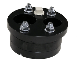 extremely cost effective and there is an option to add stainless steel hardware if your application calls for that. Another benefit is that they are available in both solid and split plate design making it likely that there is an ABS well seal that will work with your required application. Unfortunately, they are not suitable for deep pipe sets greater than 300′.
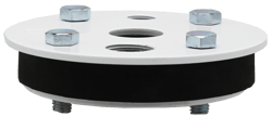 They are typically available in sizes all the way up to 12″ and are significantly stronger than cast iron or ABS. They are however, usually higher in cost and smaller sizes have thinner top plates compared to the cast iron and ABS well seals.